The most important step in the process has been done, or at least started, which is: defining the high level specification of your mechanism. Great, now it’s time to get specific with the details. In this step, we’ll define the required torque specs that will allow you to actually start searching on the catalogs.
This is the second post in the series The Ultimate Stepper Motor Selection Guide. Click here for the table of contents.
Step 2: Define your “Pull-Out Torque” requirements
OK, this is the meat, the bacon and potatoes. The gold medal. The big tamal. You have to pay real attention to this part of the process. Here’s where you win or lose as a mechanism designer. Miscalculating your torque requirements will give you a weak and incapable mechanism or an unnecessarily over-sized one (no, we don’t say “over engineered” in this blog).
Once you have the high level spec of how you want/need your mechanism to perform, it’s time to bring it down to very specific numbers. In the case of your stepper motors, you need to translate the spec to torque values at the specific RPM you want your motor to spin.
But if you’ve looked at stepper motor catalogs, you’ve noticed that there are three major torque specs being called out: Holding Torque, Pull-out Torque (in the form of a graph), and the Detent Torque. So let’s go one by one.
A Torque value at a specific RPM is called the “Pull-out torque” in the stepper lingo, and this is the number you should be using when talking to your stepper motor vendors. It is really important that you determine your pull-out torque requirement, since most of the times all you get as a spec is the motor’s “Holding Torque”.
Why is knowing the Pull-out Torque more important than knowing the Holding Torque? Only because the Holding Torque is the theoretical torque your motor can supply at 0 RPM or when it’s holding its position, which could mean nothing to you if you only care about a motion. Also, as we will learn later, stepper motors have limited operational ranges (usually low RPM), so knowing your output spindle’s RPM and torque will very quickly narrow down the options you have.
Also, even though the Holding Torque is the most common spec, it only matters when you’re using your stepper to hold your mechanism in a specific position (like the position of the model base of a 3D printer, the height of the Z axis of a CNC mill, or the angle of an actuated door). But it’s most likely that you can get around that with lead screws, other non-backdriveable gear trains, breaks, etc., and what you really want is to use your motor to rotate with certain torque at a certain speed, and that’s the Pull-out Torque.
So, how do we calculate or find this value for our motor? The way I find to run this process more efficiently is to do a Top-Down calculation. Start from the requirements of your output spindle (Top) and traverse your gear train all the way to your motor (Down). Again, this my sound obvious to some, but it’s not always the case.
Start by determining how much torque you need at the output or end effector based on Thy Spec and add a Torque Margin. Your Torque Margin is any extra torque you want your mechanism to have so that you’re not continuously operating your motor or other components at their max specs. It can also be called a Safety Margin, or Service Margin. A 25% Torque Margin can be plenty enough. It all depends on your application, and other unknowns such as friction, inertia, future-proofing, or use error.
Based on your application you may need to have more or less of a Torque Margin. Just make sure that when you calculate your joints and components, you make sure they are able to take the 100% of the torque, which equals the Pull-out Torque + Torque Margin.
Next, looking at Thy Spec, determine the specific RPM that you need your spindle or end effector to spin at while applying that torque.
Looking at both torque and RPM, go down through your drive train multiplying or dividing. You may or may not have a good idea of what kind of gear reductions (if any) you need here, but you can start with an arbitrary ratio and see what kind of motor that gives you. You’re not looking at any specific gear train design here just yet, we’re in an earlier, analytical phase that will help you define it.
This is an iterative process of optimization. You may find that a low gear ratio gives you a decently sized motor for your application but not enough resolution, or vice versa. So play with the numbers here (an Excel table will come really useful). Keep Thy Spec handy and look at all the things your mechanism needs to achieve, mainly: torque, speed and resolution. Increase or reduce the gear ratio until you have something that makes sense for all your specs. A sample table could look like this:
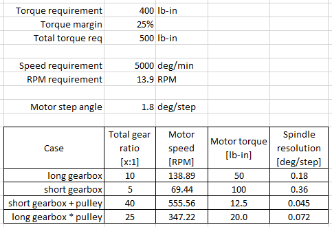
I the sample table above, it looks like a gear ratio of around 25:1 would do a good job. Steppers are better at low RPM ranges and don’t necessarily output too much torque. But also the resolution is greatly improved. 0.072 deg/step could be a pretty good resolution depending the application.
While going through this exercise for the DIWire, I ended with a much more detailed table like the one above, in which I also added torque values from different vendors, torque curves, shaft and bearing calculators, belt calculators, etc., for all of the machine axes. Such table allowed me to quickly iterate through my conceptual drive train and quickly and effectively determine what motors and vendors I wanted to look at in more detail.
So, after looking at the drive train, when you reach the motor, you’ll know the torque that the motor needs to supply and the speed it needs to rotate at, a.k.a., you’ll know the pull-out torque you need.
It’s also common that mechanisms will be asked to move at more than one operational parameter (speeds), so once you know how to run the process, repeat the calculation described above for both of your torque and speed extremes (slow and fast) or for all of your points of interest in your speed-torque spectrum and boom! You have a motor spec. Voila!
At this point we now know the motor’s required pull-out torque and holding torque (if it’s needed), and you should be able to narrow the catalog search. But what about the Detent Torque?
Right, steppers also have another very common spec called the “Detent Torque”, which is the torque required to defeat the “detent”. I know, bear with me.
In stepper motors, the “detent” is the force created by the permanent magnets of the rotor being attracted to the iron poles of the stator, and can sometimes be used as the force to hold your mechanism in place. But, depending on your application, this could mean nothing to you or could actually be hurting you.
This is because the Detent Torque will always be against you when you’re spinning. The faster you spin, the more magnets are attracted to more poles, more energy is required to defeat the detents and therefore less Pull-out Torque can be extracted out of the motor. This explains why the stepper motor torque curves look like downhills, dropping very quickly.
So while it may look really cool to have a motor with a nice and strong detent torque of 12N.cm (about 1lb-in), you may end up with an overall weaker motor, or with a motor that has a very limited RPM range, or needing an oversized driver and higher-voltage power supply to achieve the same results.
And there you have it. After a few tries you’ll have a configuration that will make sense to you, and you’ll have an initial specification of your motor that will allow you to look into the catalogs. This is why this step is so important. We’ll talk about the vendors later on, but this initial set of numbers kickstart a big portion of the detail engineering work that follows, including the specification of bearings, shafts, mounts, belts, structural members, etc.
Missing your torque margin, overlooking the detent torque, focusing on the holding torque, looking at only one spec (torque) instead of at the complete set, etc., are common mistakes that can be avoided by being as thorough as possible with this initial analytic step.
So, is this it, are we done? Well, not really. At this point we have a spec for a motor, but we haven’t looked at the catalogs just yet so we don’t know if such motor exists or not. We have defined a gear reduction, but we don’t know how that looks like, etc. So, let’s continue with the process. The motor torque spec is known, let’s look at its accuracy and resolution.
Oscar
This is the second post in the series The Ultimate Stepper Motor Selection Guide. Click here for the table of contents.